This Post contains:
Bed Platform
Bike Rack
Cargo Area Lights
Cell Phone Mount "Off Roam"
Cellphone Booster/Amp "WeBoost "
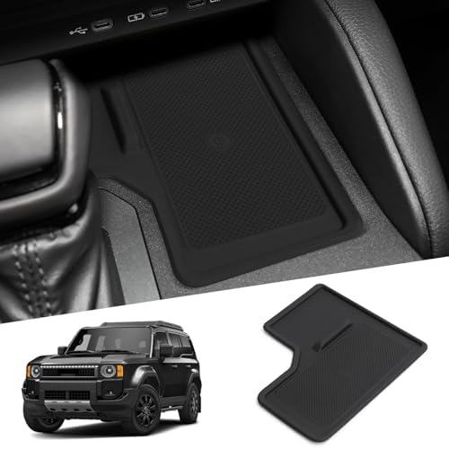
Center Console Lid
Center Caps
Credit card Key
Door Pull Lights
Bed platform Mod:
I didn't want a full sized, dedicated platform, I still need the seats for traveling with my G-Baby. I wanted something super lightweight that could be stored on it's edge, if needed or strapped to the roof rack, if needed. I wanted clear unobstructed storage under it to store my tool kits and access to the rearmost storage tray. I made and installed a carbon fiber deck. (edit: after finishing the carbon fiber deck, the entire platform weighs 13 lbs)
When I measured the 1/2 folded seat front edge and rear edge, there was 1.5" - 2" difference in height so I made my platform 3.75" tall. That leaves 1.5" or so difference in height and I don't think it'll be an issue.
It's only 4" tall, just enough for my jumper cables and socket set will fit underneath. I didn't use what most are using to secure the platform to the cargo floor (turn buckles) I made some 1/8" thick by 1.5" wide metal straps that take advantage of the large bolts holding the hybrid battery to the frame. I used some 1" nylon strap secured the mounts/metal strap mentioned above, cut some very small slots in the plastic trim pieces and threaded the nylon through those. I attached the quick cam buckle to the bed. When the bed isn't installed only two nylon straps are visible in the cargo area and those are easily pulled through the rubber mat and hidden.
I also hinged the top deck at the rear storage tray area, allowing me to flip it up and gain easy access to the tray
The straps allow me to remove the bed in approx 3 min. They also allow me to unbuckle the rear straps and pivot the bed up to retrieve the jumper cables or my socket set.
View attachment 59711View attachment 59746
Extruded Alumim Frame
View attachment 59747
Mattress inflated, fits like a glove
View attachment 59748
Mattress from amazon ($100) Someone on this forum recommended this, and they weren't wrong, I like it so far.
View attachment 59749
The Key to a sturdy extruded alum frame structure are exact lengths and 90 degree cuts. (wood working tools work great for cutting alum, just go slow and keep a firm grip, the metal will get hot, so gloves are recommended)
The ext Alum is 3/4" square (actually sold in mm)
The long runners are 42" for the top two and 34" for the bottom two (allows for the rear seat to be reclined in a normal sitting position with the rack installed). The bottom runners are shorter to allow access to the rear storage tray with the rack is installed.
The cross braces are 25.5" and are installed between the top runners.
The vertical posts are 1.75" and are installed between the top and bottom rails. (this allows for the 2 different style corner braces to be installed)
Bike Rack:
I purchased a e-bike and needed a bike rack etc..........
I chose the "Cravot" for aprox $260.00 it was decent for what I paid but there were several things I wanted to change.
1 - It stuck way out from the bumper.
2 - The receiver fit was sloppy, which most receiver mounts are.
3 - The included ramp didn't lock on to the rack well and would slip off.
4 - The height of the rack when installed in the receiver was awkward for me to load my bike on.
5 - The swing up arm for holding/securing the bike's frame was awkward.
6 - No way to lock the bike to the rack.
7 - The LC's anti-back up feature engaged with the rack installed.
The cons:
You have to be careful when raising the rack with the bike on it or the cross bar will snag on the top post (have to lean the bike away about 3 degrees as it gets to the top of the travel).
It's a little on the slow side.
The only thing I would have done differently........... I should have mounted the jack 90 degrees (sideways) from how I did it. I ended up moving the up/down switch from facing the hatch (factory location) to the side for easier activation, while holding the bike while it lifts into the fully raised position.
https://www.amazon.com/dp/B0D2VXFZ8X?ref_=ppx_hzsearch_conn_dt_b_fed_asin_title_1&th=1
View attachment 59750
(1 and 5) - I cut the swing up arm off the bar completely and removed approx 10" - 16" from the length of the bar. This created another issue of opening the LC's rear hatch with the rack installed. To solve this I purchased a hitch extender from Home Depot, cut that into three parts and used the parts along with some 3/16" plate to make a tilting mech.
(2) - I drilled out the stock 5/8" lock pin holes to 1". I used some 1" round stock to make some slugs and drilled, tapped (to 5/8") and welded the slugs into the receiver tubes ( one for the bumper and one for the new tilt mech). I used some grade 8 bolts and machined some new "screw in" lock pins, which eliminates the receiver slop.
(3 and 4) - I saw a "Lift Caddy" but wasn't paying the $700 for it, so I bought a "electric trailer jack" from Northen Tool for $150.00 and promptly cut that up and welded part of the receiver extender from the previous fix, to the jack tube.
(5) - I fabbed a plate that bolted between the trailer lift motor and the jack and mounted a non-movable arm that the bike's frame secures to (utilizing the Cravot piece).
(6) - Welded a piece of 1/8" pipe to the jack tube that the NY lock slips into and the chain wraps around the bike frame tec.... but allows the lock to be removed from the rack and taken with me.
View attachment 59751
View attachment 59752View attachment 59753
View attachment 59754View attachment 59755
(7) Which took several attempts to solve. 1st I tried just a light bulb to the "Blue wire" (trailer brake) with no joy. So I thought maybe all the lights had to be hooked to the 7 pin for it to work, again no joy. I ordered the cheapest electro brake magnet I could find (see link below) hooked that up and it worked! Anti-back up disengaged when the 7 pin was hooked up. Figured I might as well add a back up light....... LOL so now my rack is powered up and down, full running, turn, brake and back up lights. I had to mill the magnet housing down in order for it to slip inside and be bolted to the rack receiver tube.
Red lines indicate the area I milled off, in order for it to fit inside the receiver tube.
https://www.etrailer.com/Accessories-and-Parts/etrailer/AKBRKR-M7.html
7 Pin trailer plug "blue wire". Be aware different people use different wire colors. The important part is the pin location.
View attachment 59756
Cargo area lights:
I purchased 2 of these from Amazon, milled off the little bars that are used for a strap around a roll bar. Fabricated a mounting plate that fits under the OEM grab handle. They work Great!
View attachment 59757View attachment 59758View attachment 59759View attachment 59760
Off Roam Cell Phone mount:
View attachment 59761View attachment 59762
WeBoost cell phone amp Mod:
Purchased the Wilson Electronics "WeBoost Overlander" cell phone amp. I welded a steel plate to the back side of the jack cradle and mounted the amp to that. I made a solid spacer that fits in the EOM roof rack "C" chanel and through bolted the Weboost antenna to that. The antenna bounces and hits the roof when folded, so I fabricated a stainless steel antenna cradle that bolted to a 3/4" extruded alum. The new alum rail is bolted to the "missing" 5th cross bar should go. I ran the coax in the corner gap of the rear hatch, through the OEM rubber boot, across to the "D: pillar and down to the Amp.
View attachment 59763
View attachment 59764
I poked a very tiny hole in the rubber boot using an ice pick, then forced the coax through that tiny hole. It made a very tight waterproof seal.
When removing the rubber boost, DO NOT attempt to pry it off like every other panel or you will break the plastic keeper! Grasp the rubber boot along the flat part of the boot and pull straight out until it come off the white plastic keeper, work around the boot until it's separated from the keeper. Once the boot is free, there are plastic tabs that keep the keeper secured to the metal, just depress them and pop the keeper out. after running your cable through the boot, stretch the rubber back around the white keeper and snap the keeper back in to the hole.
View attachment 59765
Old modified OEM panel and New Aussie 7 gang switch panel
View attachment 62551
The purpose of the relay: The original Weboost switch, switched between two points from the cigar plug circuit board (no additional 12v input) The Ch4X4 switch would provide an additional 12v input to the circuit board which would burn up the board. The relay provides the same functionality as the original switch and controlled by the CH4X4 switch.
View attachment 62320
Center Console Lid separation:
To separate the inner and outer shells only requires a phillips head screwdriver.
1 - Use a plastic trim tool, insert it at the seam of the rear AC control panel and the bottom Shoe. (what I call the "shoe"). Once it pops, grasp the panel on each side of the AC panel and give it a good yank straight rearward. It'll pop right off.
2 - Use a #2 phillips screwdriver and remove the six mounting screws.
Full disclosure...... steps 1 & 2 are not required, but that's how I did it.
View attachment 59767
3 - Open the lid and use the trim tool, insert it in the small gap on the rounded corner, between the top cover and the lower inner cover and twist the tool to start the separation. Insert a second trim tool and twist, working your way down the panel.......... repeat for the other edge.
View attachment 59768View attachment 59769
Center Cap Mod:
Bought some Center Caps took them apart, painted them with "Ford Dark Shadow Gray" touch up paint.
View attachment 59770View attachment 59771
Credit Card Key:
Parts are for a 2024 Tacoma..........
New credit card key, 8990H-A1010
Emergency key blank, 69515-12350
Not every locksmith can cut this key.
Program new card to vehicle.
View attachment 59772
Musts:
Brand new never programed credit card key
Bring all the existing fobs when getting the card programmed, otherwise any forgotten fob will not work anymore. They need to enter all existing key registrations into the vehicle at the same time.
Door Pull lights:
Toyota Inner Car Door Handle Mini Bowl Lamp
View attachment 59773
Actual installed light:
View attachment 59774
I spray painted the edges black because the ones I used in my Taco were too bright. The FE comes with OEM door pull lights and in reality, I just wanted the “Land Cruiser” logo for the cool factor.
I didn’t want to hack the OEM wiring and decided to make some “break-out” harnesses…… I knew from a previous install that I had to leave some slack in the wiring in order to install the door pocket trim panel screw and I added a third connector to allow the light to be disconnected from the “break out” harness.
View attachment 59826
I purchased several different door light wiring harness connectors from Amazon to make the “break out” harness. For the “Female” pin connector (I purchased these two):
Amazon.com: automotive connectors 2 Pin 7282-5845 7283-5845 7282-5846 90980-11918 Automotive Ambient Light Cable Socket easy replacement(Female,5PCS) : Automotive
Buy automotive connectors 2 Pin 7282-5845 7283-5845 7282-5846 90980-11918 Automotive Ambient Light Cable Socket easy replacement(Female,5PCS): Harness Connector Repair Kits - Amazon.com ✓ FREE DELIVERY possible on eligible purchases
www.amazon.com
View attachment 59776
Amazon.com: 1/5/10/20 Sets 7282-5845 7283-5845 unsealed 2-pin Automatic Reader Coil Socket Female Male Connector Foot Socket Light(White) : Automotive
Buy 1/5/10/20 Sets 7282-5845 7283-5845 unsealed 2-pin Automatic Reader Coil Socket Female Male Connector Foot Socket Light(White): Accessories - Amazon.com ✓ FREE DELIVERY possible on eligible purchases
www.amazon.com
View attachment 59777
For the “Male” pin connector: some el-cheapo door lights from Amazon. These were a little spendy but after comparing the cost of new housing, pins and shipping, these were close in cost ($9 per). I cut off the connector wires as close to the light as possible and I’ll repurpose the light on other projects.
Amazon.com: LED Luggage Compartment Light Fits for Toyota RAV4,Trunk Ceiling Lights Lamps,Decorative Atmosphere Lamp,Interior Replacement LED Lights Lamps,Car Accessories (for Toyota RAV4 2022-2025) : Automotive
Amazon.com: LED Luggage Compartment Light Fits for Toyota RAV4,Trunk Ceiling Lights Lamps,Decorative Atmosphere Lamp,Interior Replacement LED Lights Lamps,Car Accessories (for Toyota RAV4 2022-2025) : Automotive
www.amazon.com
View attachment 59778
Completed breakou harness:
View attachment 61921
Do
NOT buy these, they took forever to arrive and they didn’t include the metal terminals
Amazon.com: 2-Pin Female Male 7283-5845/90980-11918 7282-5845 Automotive Reader Coil Connector(Male Female Set,10sets) : Automotive
Buy 2-Pin Female Male 7283-5845/90980-11918 7282-5845 Automotive Reader Coil Connector(Male Female Set,10sets): ECM Wiring - Amazon.com ✓ FREE DELIVERY possible on eligible purchases
www.amazon.com
View attachment 59779
These are
NOT the correct ones either……
Amazon.com: iJDMTOY Pair OEM-Spec Side Door Step Courtesy Light Power Cord Pigtail Connector Harness w/ 5-Inch Wiring Compatible with Lexus/Toyota/Scion, Compatible with Subaru : Automotive
Buy iJDMTOY Pair OEM-Spec Side Door Step Courtesy Light Power Cord Pigtail Connector Harness w/ 5-Inch Wiring Compatible with Lexus/Toyota/Scion, Compatible with Subaru: Wiring Harnesses - Amazon.com ✓ FREE DELIVERY possible on eligible purchases
www.amazon.com
View attachment 59780