🛠️ Member Build Eod Guy's Ride

Member Build

EOD Guy

Moderator
Staff member
📛 Founding Member
Feb 5, 2024
2,815
Media
382
3,764
Alabama
Vehicles
LC/FE
Air Compressor Mod: Pic A/C - Viair 485C
Air Compressor.jpg

Yellow dots are factory bolts/holes
Air Compressor 1.JPG


Mounting plate, used some stand-offs under the bolts to make it level
Air Compressor 2.JPG


Compressor mounted
Air Compressor 3.JPG


Switch is from "CH4X4" (cube size)
Air Compressor 4.JPG


Air tank mounted, it's tight but it fits
Air Compressor 5.JPG


Chuck, pressure switch installed. I use a small tank, not for air storage volume but to take advantage of an air pressure switch. That way the compressor doesn't run non-stop. I also use a "pressure relief valve" in order to not burst the tank.
Air Compressor 6.JPG


Passenger side Pwr Distro box, corner cover removed showing the main feed and starter cable lugs. At the top of the pic are the ribs that I removed in order to put the extension in.
Air Compressor 7.JPG


Ribs removed
Air Compressor 8.JPG


Paper template of the new buss bar extension
Air Compressor 9.JPG


Stainless Buss Bar extension, 1st bends
Air Compressor 10.JPG


Stainless Buss Bar extension, Finial crimp on to 6 gage wire
Air Compressor 11.JPG


Stainless Buss Bar extension, mounted
Air Compressor 12.JPG


Stainless Buss Bar extension, with OEM cover back in place. You can see the red 6 gage wire along the left side of the PDC, it's routed to the area in front of the air cleaner box
Air Compressor 13.JPG


Circuit Breaker and Aux Buss Bar mount
Air Compressor 14.JPG

Air Comp Wiring Dia.jpg


Yellow dots are bolts/screw, Red dots are tabs.
Under dash 1.JPG


Door weather stripping must be pulled away 1st (Yellow dots) then the side panel can be pulled off (yellow dots are approx where the plastic clips are, the Green dot is a plastic hook that must be inserted 1st when you reassemble.
Under dash 2.JPG


Pull straight out on the switch panel for removal. I spliced into the illumination wire (green wire coming out of the rheostat and actually spliced in where there was room).
Under Dash 3.jpg

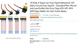
Pushed the switch and the air compressor works like it's supposed to! I used a fuse tap in an empty ACCY slot to power the Air Compressor switch (which in turn energizes the relay).

Lighted Door Sills Mod: Took about 15 minutes, Yellow dot is the wiring plug (passenger side is in the same location) a hook tool is the best tool to unlatch the blanking plug. The Blue christmas tree fastener stayed in when the OEM sills were removed, you will need to remove it before you install the lighted sill (new ones are already mounted in the new sill).
Door Sill 1.JPG
Door Sill 2.JPG
Door Sill 3.JPG


Center Cap Mod: Bought some Center Caps took them apart, painted them with "Ford Dark Shadow Gray" touch up paint.
Center Cap 1.jpg
Center Cap 2.jpg
 

Attachments

  • Interior Trim panel removal.pdf
    7 MB · Views: 135
Last edited:
  • Thread starter
  • Moderator
  • #2
Relay Box Mod: As always you need extra protected circuits to run Winches, lights, air compressor etc....

I have used this relay box on several different vehicles and have been very happy with it. I have de-pinned (removed all the normally closed (blue) wires) and re-wired the #1 (40amp) relay ground to have it's own ground vs the built in ground buss.
Relay Box.jpg


Mount made out of 1/16" alum
Relay Box 2.JPG


Mount installed making sure not to touch the ABS lines
Relay Box 3.JPG


Relay box installed
Relay Box Wiring.jpg

Relay Box 4.JPG


Routing of the Relay box power supply main wire to the 12v Buss bar (installed in front of the air filter box).
Relay Box 5.jpg


The yellow wire will power a relay that will power a ASSY buss bar (buss bar will be in the cabin). I will hook the yellow wire to one of the unused "key on" fuse blanks.
Relay Box 6.jpg


There is a removable plug to the right of the brake booster almost to the cowl, approx 1/2" in diameter....... it's easily removable and will allow 8, 16 gage wires to pass from the engine bay to the cabin. Harbor Freight gromet kit has the exact grommet to protect the wires......

Horn Mod: I couldn't like the "meep meep" horns, The Toyota premium (08522-60010) sound much louder and better!
Horns.jpg

Rear Hatch Light Mod: I was in the back and the curtesy lights in the rear hatch would not go off. Removed the rear hatch trim piece and installed a switch in the power side of the existing curtesy light wiring. I super imposed a rough outline of the existing and new wire runs.
Rear Hatch 1.jpg
Rear Hatch 2.jpeg
Rear Hatch 3.JPG
Rear Hatch 4.JPG
Rear Hatch 5.jpg


Lug Wrench (Metric), not really a Mod but it's hands down the best and most compact lug wrench I've ever owned!
Lug Wrench3.jpg


Magnetic Unlocking Mod:

I use a magnetic sensor to unlock the driver's door with any metal object. Basically the sensor produces a Neg pulse when a metal object passes over it, the range is only about 1/4". I keep a spare fob (in sleep mode and in a faraday pouch) hidden in the interior, so I'll never be stranded due to lost keys.
Magnetic Proximity Switch.jpg

It's a three wire hook up.
1 - (Brown) 12v always hot, easy (see picture below)
2 - (Blue) Ground
3 - (Black) Output to the trigger wire on the driver's door. Had to take half the truck apart to gain access to the proper wire, it was a royal PITA!

Radar Det Mount Mod:
This was quite the adventure, several variations and settled on this one.
The switch is a Redline 360C switch taken apart, switch and LED wires extended and mounted in the OEM blanking plug. Switch is a motorcycle after market mini-horn button colored with a sharpie, I don't like the color so I'll be painting it in the future. (edit) I found some 8mm black mini switches and replaced it with one of those.

The holder is a cell phone mount. The post is fabricated from parts of the cell phone holder and a 1/4 x 20stainless screw rethreaded on one end to M6 to allow the magnet to be screwed on. The adhesive disk is stuck to the dash, the adhesive disk was a bust, soon as the sun heated it up, it quit sticking. The solution was to remove the speaker grill (pulls straight up) grind down the ribs on the bottom side and epoxy a metal plate (black item on the L/H side) to the underside of the speaker grill. Radar mount 4 pic is the magnet (65 lbs) holding the Radar Det and mount upside down. It'll hold well for everyday driving (about 5lbs of holding force) but not off-roading. They sell a stronger magnetic base (120 lbs) that may hold better.
Radar 2.JPG
Radar Mag Mount.jpg
Radar Mount 5.JPG
Radar Mount 4.JPG


The power and ground wires are ran under the dash area to the OEM switch panel area (that's where all my add on wires are ran) , up the L/H side to the Instrument trim bezel. I pulled out the bezel enough to run the wires around it to the center speaker area of the dash and just let it exit there. Snapped the bezel back in and made for a nice tidy wiring for the radar det.

Radio Knob Mod: part# 90010-23059
I did the RAV4 radio knob swap on my Taco and Liked it. I did the RAV4 swap on the LC and like it as much. No tools are needed, just pull the OEM knob off, remove the spacer/beauty stand off from the RAV4 knob, push the RAV4 knob onto the radio shaft.

RAV4 Knob with the insert removed from the backside.
Radio Knob1.JPG


RAV4 knob installed
Radio Knob3.JPG
 

Attachments

  • Fuse Taps 2.jpg
    Fuse Taps 2.jpg
    116.6 KB · Views: 159
  • Fuse Taps 3.jpg
    Fuse Taps 3.jpg
    154.6 KB · Views: 166
Last edited:
  • Thread starter
  • Moderator
  • #3
12V outlet Mod:
I wanted a 12v outlet in the rear that was easily accessible. I fabricated a simple mount from a piece of angle iron, bolted it to the Jack cradle. Jack trim cover closes completely without any interference. I added a very small voltage meter, that's momentarily turned on by pressing the switch. I also added a battery tender pig tail in the rear to provide an easy power source, ease to hook up my jumper box (I don't need the starting power of the jumper box, just the 12volts to get the LC's computers fired up so the Hybrid battery can take over and start/charge the vehicle) As always, I protect my wiring with a resettable circuit breaker. I went with a 30amp as I don't anticipate running anything with a higher amp load.
CB4.JPG
CB1.JPG
CB2.JPG
12v outlet 2.jpg


Seat Storage: I purchased 3 or 4 different types of seat gap fillers/storage etc.......

I thought "storage 1" pic was the answer..... nope, it collapses and slides with the seat, not very deep and really would only hold a cell phone a bottle of water and putting that bottle back in while driving was interesting! so I purchased yet another set ("Pocket" pic)and fixed mounted them to the knee bolster pads. That way no adhesive to worry about on they actually will hold things.....LOL I used 1/2" binding posts (used to hold "hole" punched papers together) Yellow circles are where I drilled from the back side and through bolted/mounted them to the knee bolster.
Storage 1.JPG
pocket 2.jpg
Binding posts.jpg


Roof Rack Step:
Initially I didn't think I'd be using the roof rack for anything and actually considered removing it. My daughter convinced me "It completes the look of an "LC" so I left it on. I decided to mount my WeBoost antenna to the inner frame as it was very solid. The antenna has a locking folding feature that allows it to be stored when running through a car wash and or when parking in areas where you don't need unwanted interest in the vehicle. All very well except when you're not very tall and old and climbing up on a tire isn't as quick as it used to be.......... so I saw a solution on Amazon, but it was made of steel (which will rust over time) and I wasn't going to pay $100+ for something I didn't really like. I decided to make my own version out of extruded aluminum that would fold flat, easily stored and double as a small table when rested on the bumper vs the tire.
Step1.jpeg


My result.... It's 22" wide, heavy duty and has enough room on the platform, unlike a small ladder, that I can easily turn around, reach almost to the front of the rack, weatherproof and easily stored in the cargo area. It'll get either powder coated or painted in the near future.
Step 2.jpeg


Rear Bumper Covers:

Remove the top bumper cover (it pops straight up, no tools required) you can look into the small slots (where the top cover snapped into) and see the white keepers. A long skinny screwdriver is just right to depress the white tab and push it to the side (see picture below). Getting them out wasn't a big deal.
Bumper Cover 2.JPG


To re-install them was challenging, I used a long set of forceps for the top ones except the inner most one on the Pass side required a hole drilled. After the hole was installed.....lol It was easy as pie.
Bumper cover 3.JPG

Bumper Cover.JPG


Bed platform Mod:
I didn't want a full sized, dedicated platform, I still need the seats for traveling with my G-Baby. I wanted something super lightweight that could be stored on it's edge, if needed or strapped to the roof rack, if needed. I wanted clear unobstructed storage under it to store my tool kits and access to the rearmost storage tray. I made and installed a carbon fiber deck. (edit: after finishing the carbon fiber deck, the entire platform weighs 13 lbs)

When I measured the 1/2 folded seat front edge and rear edge, there was 1.5" - 2" difference in height so I made my platform 3.75" tall. That leaves 1.5" or so difference in height and I don't think it'll be an issue.

It's only 4" tall, just enough for my jumper cables and socket set will fit underneath. I didn't use what most are using to secure the platform to the cargo floor (turn buckles) I made some 1/8" thick by 1.5" wide metal straps that take advantage of the large bolts holding the hybrid battery to the frame. I used some 1" nylon strap secured the mounts/metal strap mentioned above, cut some very small slots in the plastic trim pieces and threaded the nylon through those. I attached the quick cam buckle to the bed. When the bed isn't installed only two nylon straps are visible in the cargo area and those are easily pulled through the rubber mat and hidden.

I also hinged the top deck at the rear storage tray area, allowing me to flip it up and gain easy access to the tray

The straps allow me to remove the bed in approx 3 min. They also allow me to unbuckle the rear straps and pivot the bed up to retrieve the jumper cables or my socket set.
Bed Strap 1.jpeg
Bed Strap 2.jpeg


Extruded Alumim Frame
Bed1.JPG


Mattress inflated, fits like a glove
Bed2.JPG


Mattress from amazon ($100) Someone on this forum recommended this, and they weren't wrong, I like it so far.
Bed3.jpg


The Key to a sturdy extruded alum frame structure are exact lengths and 90 degree cuts. (wood working tools work great for cutting alum, just go slow and keep a firm grip, the metal will get hot, so gloves are recommended)
The ext Alum is 3/4" square (actually sold in mm)
The long runners are 42" for the top two and 34" for the bottom two (allows for the rear seat to be reclined in a normal sitting position with the rack installed). The bottom runners are shorter to allow access to the rear storage tray with the rack is installed.
The cross braces are 25.5" and are installed between the top runners.
The vertical posts are 1.75" and are installed between the top and bottom rails. (this allows for the 2 different style corner braces to be installed)

Credit Card Key:
Parts are for a 2024 Tacoma..........
New credit card key, 8990H-A1010
Emergency key blank, 69515-12350
Not every locksmith can cut this key.
Program new card to vehicle.
Credit card key.jpg

Musts:
Brand new never programed credit card key
Bring all the existing fobs when getting the card programmed, otherwise any forgotten fob will not work anymore. They need to enter all existing key registrations into the vehicle at the same time.

Secure Box Mod:
I made it out of 3/16" cold rolled steel. Fingerprint lock.
Secure Box 2.jpeg
Secure Box 3.jpeg


Cargo area lights:
I purchased 2 of these from Amazon, milled off the little bars that are used for a strap around a roll bar. Fabricated a mounting plate that fits under the OEM grab handle. They work Great!
Light 1.jpg
Light 2.jpeg
Light 3.jpeg
Lights.jpg


Solar 12v battery Charger MOD:

I don't use my LC for a DD and I've had the 12v battery go flat several times, so much that I bought a jump box. If it sits for more than a couple weeks the battery voltage drops below the min required to fire up the computers and it will not start. With the jump box it has always started right up, but even with a new Optima battery there is always a constant drain so I decided to see if I could fix it............
Solar Charger.jpeg


I mounted the panel under the cross bars in order that I still had full use of them. I ran the wire the same way as I did my "WeBoost" coax cable just on the Dvr's side.
 
Last edited:
  • Thread starter
  • Moderator
  • #4
WeBoost cell phone amp Mod:
Purchased the Wilson Electronics "WeBoost Overlander" cell phone amp. I welded a steel plate to the back side of the jack cradle and mounted the amp to that. I made a solid spacer that fits in the EOM roof rack "C" chanel and through bolted the Weboost antenna to that. The antenna bounces and hits the roof when folded, so I fabricated a stainless steel antenna cradle that bolted to a 3/4" extruded alum. The new alum rail is bolted to the "missing" 5th cross bar should go. I ran the coax in the corner gap of the rear hatch, through the OEM rubber boot, across to the "D: pillar and down to the Amp.
WeBoost mount.jpg
Antenna mount.jpeg


I poked a very tiny hole in the rubber boot using an ice pick, then forced the coax through that tiny hole. It made a very tight waterproof seal.

When removing the rubber boost, DO NOT attempt to pry it off like every other panel or you will break the plastic keeper! Grasp the rubber boot along the flat part of the boot and pull straight out until it come off the white plastic keeper, work around the boot until it's separated from the keeper. Once the boot is free, there are plastic tabs that keep the keeper secured to the metal, just depress them and pop the keeper out. after running your cable through the boot, stretch the rubber back around the white keeper and snap the keeper back in to the hole.
Boot2.jpg
sw panel.jpeg


Optima Battery: DH6
Optima Battery 2.jpeg


Puddle Lights for the doors and rear hatch light for S&Gs.
Puddle Light.jpeg


Hood Strut Mod:
The one sold by "Sticker Fab" not a high quality kit but will do the job. We'll see how long it lasts.
Hood Strut Install 3.jpeg
Hood Strut Install 4.jpeg


EcoFlo Fridge and power bank platform:
I use my LC for other things besides overlanding........ I wanted a lightweight, easily removed and secure platform to strap the Fridge and pwr bank to. I didn't want to remove the rear seats etc....... so with the dvr's-rear seat folded forward, I took advantage of the OEM seat catch anchors. Now just waiting on the new Fridge and pwr bank.

Frame with the top off. The 8 silver magnets that secure the rear portion of the top are visable on the R/H side of the pic.
Fridge Mount 2.jpeg


Rear portion of the top installed (held in place by 8 super strong magnets)
Fridge Mount 3.jpeg


Nylon lashing straps lashing the frame to the seat anchors.
Fridge Mount.jpeg


Rain Guards:
OEM part number 08162-60840
On an easy to hard scale, I'd give it a "1" super easy. The only tricky part are the little clips. The PDF attachment is for a Lexus, but close enough (note: the PDF indicates the guards attach with separate rivets, the rivets are molded into the guard).
Rain Guards.jpg
Rain Guards 2.jpg.jpeg


Step 1 - Clean the outside door frame with an alcohol prep pad.
Step 2 - Roll down the window.
Step 3 - Pull the window channel rubber seal from the upper and fwd portions (just an inch or so)
Step 4 - Test fit the guard with the white plastic still on the foam adhesive strips, once you're comfortable, peel back the fwd green pull tab about 1/2" and fold it 90 degrees (so it sticks straight up), repeat for the trailing green pull tab. Remove the two small white plastic pieces on the rear of the guard. Place the forward edge (rearview mirror end) making sure to get the very tiny tab behind the mirror trim plate. I used my fingers to align the top / rear edge and put a slight forward push on the guard while checking the leading edge (closest to the mirror) was also aligned, then pressed the top / trailing edge onto the door frame then the bottom, making sure the adhesive stuck.

Then I moved to the forward leading edge (closest to the mirror) and started pulling the white plastic strip (this is why I made the 90 fold) at the same time I made sure the top edge was aligned as I worked my way back to the trailing edge. Making sure I pressed the entire length of the guard to ensure the adhesive strip made good contact with the door frame.

Step 5 - Take the little plastic clips, pull the window rubber out of the way and snap it onto the rain guard and it will almost self align to the metal window frame. Push the rubber back into place and roll up the window.

Glass Hatch Interior Button Mod:
When camping, I needed a way to open the glass hatch for ventilation. Initially I added a button sistering the existing exterior Glass Hatch opener button but with that method the button only works when the doors are unlocked and well...... who sleeps with the doors unlocked. I know that the fob would unlock the doors etc....... but what if in the middle of the night there was an emergency and looking for the fob could be fatal...... so I tapped directly into the lock power wire so the button works regardless if the doors are lock/unlocked.

Glass Lock Ver 1 - taps into the button wires (doors must be unlocked to function)
Glass Lock Ver 1.jpg


Glass Lock Ver 2 - taps into the lock pwr wire and functions regardless of the doors being locked/unlocked.
Glass Lock Ver2.jpeg


Interior Cargo area Hatch opener/Closer Button Mod:
I sistered the dash Hatch switch with a break out harness ran to the rear "D" pillar.
Currently only functions when the doors are unlocked (but will add "door unlock" in the future)
Rear Hatch Buttons.jpeg
 

Attachments

  • Rain Guards, lexus_gx_wind_deflectors_pw162_60013_aim_005_364_0.pdf
    6.8 MB · Views: 28
  • Switch panel 2.jpeg
    Switch panel 2.jpeg
    224.2 KB · Views: 138
Last edited:
My first mod: I was in the back today and the curtesy lights in the rear hatch would not go off. Removed the rear hatch trim piece and installed a switch in the power side of the existing curtesy wiring.
Well thats cool.

Is that the sub in the prem pkg?
 
Congrats on your LC FE. I hope it’s everything you expected if not more!
 
Damn that’s exactly what I want to do with my compressor! Did you fabricate the mount etc yourself?
 
  • Thread starter
  • Moderator
  • #16
Damn that’s exactly what I want to do with my compressor! Did you fabricate the mount etc yourself?
Yes, It was pretty simple as I always use existing bolts/holes and had to fabricate some standoffs to make it level.
 
Yes, It was pretty simple as I always use existing bolts/holes and had to fabricate some standoffs to make it level.
Where did you draw power from, the relay/fuse box next to it, maybe the relay where the jump terminal is on the other side of the bay?
 
  • Thread starter
  • Moderator
  • #18
The power distro box on the passenger side, where the cable for the starter enters the box. There are two little tabs that you can depress and the corner cover comes off (corner of the box is still there but the cover covering the cable bolt lifts straight up) I'm waiting on some 6 gage cable. The brand new cable that I've had for a few years but never unwrapped, had corrosion all through it and I threw a brand new 100' roll in the trash.

Once the cover comes of you'll see the 12v feed lug and the starter cable lug. I plan to fabricate a terminal extension out of stainless to mimic the starter cable terminal and use a die grinder to make room for the new terminal and cable. Picture above.
 
Last edited:
Once the cover comes of you'll see the 12v feed lug and the start cable lug.

Is the 12v feed a power source already being used by the vehicle to power some things, or is this an extra 12v aux source for added accessories? The shop that will install my winch (and onboard air) prefers not to piggy back and add extra load to a line. They're talking about running their own 12v line from the back, but if Toyota is providing this I don't want to duplicate.
 
  • Thread starter
  • Moderator
  • #20
Is the 12v feed a power source already being used by the vehicle to power some things, or is this an extra 12v aux source for added accessories? The shop that will install my winch (and onboard air) prefers not to piggy back and add extra load to a line. They're talking about running their own 12v line from the back, but if Toyota is providing this I don't want to duplicate.
I haven't verified this, but I believe the inaccessible cable on the buss (there are two) is the main cable back to the 12v battery and the 2nd cable on the buss goes to the 12v starter motor. So in theory the 1st cables powers the two power distribution boxes under the hood. and the 2nd powers the 12v starter.

If I install a winch I may run a cable back to the battery but for the air compressor, lights and power running boards, I feel comfortable with tying into the buss.
 
Back
Top