Interior dash lights anytime illumination MOD and possible aftermarket cube switch dimming via factory dimmer.

Bad1975

Active member
Feb 19, 2025
144
Media
41
176
Washington
Vehicles
FJ40 (1975), LC250 (2025)
I've gathered the DOCs from TIS and will attempt to get the anytime dash backlighting MOD to work this weekend as time permits.

Also got ahold of the full dimmer circuit and will test its operation if I get the time as well to see if it can be made to control CH4X4 and other sources of Toyota cube switches for dimming purposes. I'm currently running an additional dimmer to dim my accessory swtiches to match OEM levels. This MOD if it works may still require an additional dimmer to match OEM brightness which I'll also check for as well.

If all goes well I'll post the information back here when done and have everything verified.

I discovered I really need the anytime dash lights this weekend when driving as some of the switches I was looking to press I couldn't read in the daylight without parking lights or above on due to how dark these are on the inside and the front side window tint doesn't help with that.
 
First half is complete and operational for anytime dash lights. Will post information in a bit on a how to.

Working on dimmer circuit now for aftermarket cube switch dimming.
 
Got everything wired up both circuits working (OEM dimmer and anytime backlights for whole vehicle) .

Will post info tomorrow if anyone wants it?


IMG_4469.jpeg
 
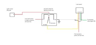
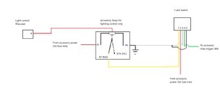
For using the OEM dimmer for aftermarket cube switches you'll need a relay with the trigger being accessory power if also doing the anytime dash light backlighting.

If not doing the anytime dash light backlighting you can wire the relay trigger into the tail circuit to achieve OEM identical function, the only issue with using the tail circuit as the trigger is the only place to tie into it is at the trailer connector as the rest of the circuit is controlled by CXPI communication (Pulse width modulation) and not normal voltage controlled. Alternatively if someone happens to have the trailer connector wiring circuit one could find out where the tail circuit voltage originates from and tie in there.

There are rubber pass throughs under both driver and passenger seats that you can remove the electrical tape from to pass additional wires through and then tape back up if wiring into the tail circuit at the trailer connector. Remove the door sill and look just under the edge of the carpet near the front of the outside seat rail and you'll find the passthrough on the inside.

Tie in point is the Red wire on pin 4 at the rheostat (see attached), you'll run that to the relay as outlined in the attached drawings
 

Attachments

  • Dimmer connector.pdf
    117.6 KB · Views: 6
  • Dimmer relay wiring option 1.jpg
    Dimmer relay wiring option 1.jpg
    53.2 KB · Views: 11
  • Dimmer relay wiring option 2.jpg
    Dimmer relay wiring option 2.jpg
    54.6 KB · Views: 9
The anytime backlight mod is a little more involved here are the connector locations on the body control module where you need to tap into and the overall circuit.

The OEM circuit is operated by the CXPI communication via an internal relay and uses the tail circuit for this (120 A circuit from the engine bay is the supply to the relay which is then protected by a 5A fuse in the body control module. If your doing this you'll be wiring in an inline fuse (5A) and a switch supplied by accessory power to turn the anytime function on or off. I hid my switch on the drivers side panel that houses the OBDII port up out of sight.
 

Attachments

  • K5 Connector location.pdf
    245.5 KB · Views: 6
  • E3 connector location.pdf
    254.5 KB · Views: 7
  • e3 connector pin 2.pdf
    143.7 KB · Views: 8
  • Dimmer illumination circuit es048.pdf
    298.2 KB · Views: 6
In the circuit schematic above your looking for the K5 connector (white housing) pin 9 (Violet wire) located at the top rear (towards engine compartment) of the body control module and the E3 connector (white housing) pin 2 (Green wire) this is located on the top front (towards passenger seat) of the body control module, sorry forgot to download a pinout for connector K5 but you can see it at the end of the circuit schematic in less detail.

All connector views from TIS are from an orientation of looking at the connector (pin side) with it removed. These connectors are locked in place with a lever much like the ECM in the engine bay, highly recommend removal of everything I removed so you can see what your doing so your not breaking the locking mechanism.

Toyota won't replace the connectors in my experience, they will sell you the parts but they aren't good at finding what you need for the connectors and pin tools to work on them either, they will however replace the entire wiring harness $$$$!
 
Method for anytime dash backlighting:

Materials:

5A fuse
Fuse tap or inline fuse
Switch or Relay
Your choice of splice and tap connectors
Smallish gauge wire

Tools:
12MM socket for negative battery terminal
10mm socket for airbag, BCM and glovebox removal
Choice of electrical tools for working wiring and connections

Optional (highly recommended):
Digital multimeter

1. DISCONNECT THE BATTERY!!! YOUR WORKING DIRECTLY ON A MAJOR CONTROL MODULE, PLEASE DONT TOUCH ANY PINS OF MODULE AND RISK STATIC ELECTRICITY DAMAGE TO THE MODULE. YOU WILL ALSO BE REMOVING THE PASSENGER KNEE AIRBAG, IF THE BATTERY ISNT DISCONNECTED YOU MAY SET AN AIRBAG RELATED FAULT WHICH WILL REQUIRE A DEALER VISIT TO RESET.

2. Remove the following trim pieces to get the glove box out.

a. passenger upper kick panel, trim panel above your feet that houses the footwell lamp if equip'd. just a couple of push to release tabs here and then you can drop the front and pull it to the rear. Be careful to disconnect the footwell light before yanking it all the way out.

b. passenger dash end trim piece.

c. passenger dash trim panel above the glove box, complete removal not required but the right side (passenger) to about the middle needs to be released from its securing clips.

d. passenger left and right side glove box trim panels, left side panel requires removal of the passenger knee pad on the center console first and the trim piece around the phone charger/storage area needs to worked loose in the front to prevent damage to a clip lock on there in order to remove the left side glove box trim panel.


Upper glove box and right side trim panels:
IMG_4467.jpeg

Clips on back of right side glove box trim
IMG_4466.jpeg


Left side glove box trim panel
IMG_4458.jpeg


Area showing where a clip lock could get broken when trying to remove left side glove box trim panel:

Note I removed all the wiring you see in this picture for the switches for adding the ebay accessory panel in this location to clean it up and used solder ferrels for all connections and with four aftermarket switches installed with the minimum wiring (combining all switch inputs) only the trigger wires to the relays are individual wires now and its still a very tight fit.

IMG_4461.jpeg


e. passenger sill panel (no photo sorry)

f. passenger kick panel, plastic nut (careful on reassembly it will strip easily) and a couple of clip locks. (no photo sorry)

With the trim pieces out of the way its time to remove the airbag, I left the wiring in place so as not to risk any possible fault codes even though the battery was disconnected.

Airbag bolts:
IMG_4463.jpeg

IMG_4465.jpeg


3. Remove passenger knee airbag, four bolts, two each side and let it rest on the floor board, there are a number of trim panel clips beneath the glove box that are quite difficult to get released to get the airbag to drop down out of the way once the bolts are removed.

Airbag removed with trim attached: (Crappy picture, didn't realize until I had it all back together)

IMG_4453.jpeg


With the air bag out of the way you are now ready to remove the glove box.

4. Remove glove box, four phillips/hex head bolts and a number of clips. I found it easier to remove by removing the interior shelf and filter access panel. You can pull via where the filter access panel was to help release the clips and you can get a decent view of what your releasing through the panel that was removed earlier. Careful to not pull out too far before disconnecting the glovebox light.

Glove box:

IMG_4454.jpeg


Glove box bolts:

IMG_4460.jpeg


Now its time to disconnect the Body control module, I chose to remove all the connectors on the front and unbolt the module to get a better view of what I was working on in the back, since there are multiple green wires it was impossible to tell which was which otherwise.

Installed BCM showing K5 connector with tap installed.

IMG_4452.jpeg


***Just a note the bottom connector on the front is the A6 connector, supply (always hot) to the BCM for the tail function which supplies the backlighting to all the buttons.

5. Disconnect all front side BCM connections

6. Remove two bolts (Bottom) and one nut (top) and lower the module down off of the threaded stud so you can rotate the module to gain a view of the top rear E3 connector. (no photo but you can find them)

7. Remove E3 connector from BCM, release locking tab and rotate lock to remove.

E3 connector and tap point pin 2 green:

IMG_4444.jpeg


Now your looking for a green wire (photo above) on pin 2 and pin 2 is in the first row on the left, second from the bottom when looking at the pin side of the connector with it removed. This will be the first tap point and these tap wires will go to your switch/relay (your choice).

8. Install tap in wire on pin 2 at E3 connector and test for good connection (continuity/resistance, should be 1 Ohm or less).

9. Once tap wire is installed at E3 and tested good reinstall E3 connector and BCM.

K5 connector tap point:

IMG_4449.jpeg


IMG_4451.jpeg


BCM removed:

IMG_4446.jpeg


IMG_4445.jpeg


Now your looking for a violet wire on the K5 connector (photos above) on pin 9 and pin 9 is in the right hand row nine down from the top on the K5 connector which was removed earlier from the front side of the BCM (top most connector).

10. Same procedure as before install a tap wire onto pin 9 and test.

11. Upon both wires testing good reinstall all front side BCM connectors.

12. Route and join these two tap wires together and connect to the output of your switch of choice or relay of choice. Your switch or relay input will be from accessory power to have the ability to have the lights on all the time (relay) or controlled (switch).

13. Connect an inline or fuse tap with 5A Max fuse to accessory power source, the fuse is a must to protect the dash lighting circuit since your now bypassing the OEM 5A protection. Connect the accessory power from the fuse to your input of the switch/relay of choice and the output of the switch/relay to the tap wires.

Your now ready to temporarily reconnect the battery to test function.

14. Temporarily reconnect battery and test for proper function. Turn on the vehicle, if you used a relay the dash lights will automatically turn on now with the headlight stalk in DRL off or the off positions, if you used a switch and the vehicle is on the same will occur but you can also turn them off and restore the function to OEM and watch the lights turn back off.

To further test functionality turn the headlight stalk to Auto and place a bright light over the light sensor on the dash, you may have to turn the vehicle off and then back on after placing the light over the sensor if in a garage to get the headlights to turn off and see if the circuit is still keeping the lights always on (relay) and is able to be switched on and off (switch).

15. Disconnect battery and do the reassembly in reverse.

16. Reconnect battery and retest for proper function.
 
Last edited:
Please let me know if anything or all of it is confusing, lot of stuff going on for this one!
Switch method for anytime dash backlighting.jpg
Relay method for anytime dash backlighting.jpg
 
Last edited:
Update, side affect the tail lights will randomly turn on if the vehicle is shut down with the headlights in auto with the lights on, ie tail function active when shutting down.

You’ll need to pull the 5A panel fuze in the BCM to prevent it.

Another possible untested solution is to wire the relay power source from battery and trigger to accessory vice both from accessory power.

Alternatively you can turn off your anytime switch that you installed but that defeats the automatic turn off feature of everything when shutting down the vehicle and too easy to forget IMO and walk back to a drained battery.
 
Back
Top